Installing The Bell Module To The Level Crossing

In a previous post, the dynamic duo, Colin C and me, installed Custom Signals Grade Crossing GCF-1 module, along with NJ International's grade crossing signal masts.  Train detection was with NCE's BD20 current-sensing detector.  Grade crossing signals, while they are nice to look at with the LED's alternately flashing, REALLY become realistic when you add sound! 

In any electronic circuitry involving lights, action or sound activated by the movement of a passing train, compatibility of the electronic unit with block detection becomes very important.  Innovative Train Technology Products (ITTP) makes a number of very compact, easy-to-install sound units that are compatible with the NCE BD20 block detector. The HQ300 series of bell-sound units are just the "cat's meow" for the kind of sound we were looking for.  The unit measures a very compact 1.4"x 2.3" which can be installed just about anywhere underneath the module.

The on-board amplifier produces 1/2 watt of sound.  Add ITT Products' 2.5" 8-ohm speaker and you have more than enough sound to warn vehicles of any approaching train, even when the speaker is installed underneath the module.  Six wires - two for power, two for the speaker, and two for the NCE BD20 current detector and the job was done.

Well,............... almost.  There's a bit of prep work to do.

We like to mount our electronic units on a 1/8" piece of Luan plywood.  This separates the unit from the module deck and makes it easy to remove if need be.  We cut the Luan at 1 5/8" wide and 2 5/8" long which provided sufficient overlap with the edges of the HQ300 unit.  We next drilled three 1/8" holes in the Luan to match the 3 holes in the HQ300.  Some 2-56 nylon screws affixed the unit to the Luan.  Since the underside of the layout is Styrofoam, a few dabs of polyurethane glue on the backside of the Luan glued the Luan/HQ300 to the layout.

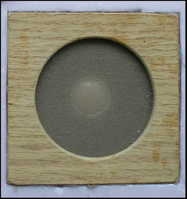
The efficient and effective operation of any sound unit depends on the "design" of speaker enclosure.  It's not enough to simply glue a speaker in place without installing it in the enclosure (You can but it's not the same.  Take a look at your Bose stereo unit to see how they produce that "Bose sound".)  The easiest way to make a speaker enclosure in the module is to use a 2 1/2" key-hole cutter to sink a round hole about 1 1/2" deep.  After digging out the centre of the circle, it was just about the right size for the speaker.  (You can produce the same hole with a utility knife and a circular disc as a guide.) 

Next, we cut another piece of 1/8" Luan plywood 4"x 4" square and then cut a 2 1/2" hole in the centre with the 2 1/2" key hole cutter.  Colin then recessed the Luan into the Styrofoam so that the speaker assembly was flush with the module deck. 

While speakers are advertised by their "effective" diameter, you have to account for additional width for the outside frame of the speaker.  Altogether, our 2 1/2" speaker measured about 2 7/8" in diameter with a 3/16" edge.  A quick trimming of the rim of the Styrofoam and Colin had the speaker sitting flush with the recessed Luan and Styrofoam.

A piece of nylon screening, along with some pantyhose over the opening, keeps poking pieces and dust out of the speaker enclosure.  Otherwise, the speaker could be readily damaged as we move our modules around. 

With everything nicely dry-fitted, Colin soldered two wires about 12" long to the terminals on the speaker and pushed them through a hole we had drilled on an angle through the Styrofoam.  Some carpenter's glue put everything together. 

With the HQ300 sound unit mounted to the underside, the 2 1/2" speaker assembly installed alongside, and the NCE BD20 block detector previously installed, we were now ready to wire everything together.

We first tapped two wires into the auxilliary power buss and ran them to the HQ300 screw terminals marked "POWER".  (Polarity doesn't matter.  Voltage can be AC or DC.  Voltage must be 9-12 volts.) 

Next up was to connect the two speaker wires to the HQ300 screw terminals marked "SPEAKER".  As the wires were longer than required, we trimmed them back so that they were snug to the module deck.  (Better to have more wire than not enough, eh!?) 

To make sure everything was in order, we jumpered a wire between Screws 1 and 2 of the MOM/LOOP terminal block.  Eureka!  Bell ringing sound!  We adjusted the orange VOLUME control until we were satisified with the loudness of the sound. 


We lastly ran two wires from Screws 1 and 2 to Screws 2 and 1 of the BD20.  VERY IMPORTANT!  Make sure that the wires from the
  • HQ300 Screw 1 is fastened to Screw 2 of the BD 20, AND
  • HQ300 Screw 2 is fastened to Screw 1 of the BD20.

We were now ready for action!  We turned on the track power, powered up the 12 volt auxilliary buss, and slowly ran a train down the tracks towards the insulated block section.

As soon as the locomotive's wheels entered the block section, the lights on the grade crossing masts started flashing

 .......AND.........  the bell started ringing!!  Eureka!!  It works! 

And as the last of the locomotive's wheels left the block section, everything went silent.

Nothing like success, eh!?  Don't ya just love it when a plan comes together.

Here's a coupla more videos of the level crossing. 

(Colin C shot these videos of the train running through the level crossing.  Ya shoulda seen the big ear-to-ear grin on his face.  Now he's thinking about cow sounds, honky tonk piano and hurdy-grudy sounds, to say nothing of the industrial sounds that can be added.  Goes to show ya that the sky's the limit, eh!?)

The Peco Electrofrog - Circuitry

The electrical routing of the Peco Electrofrog is as different from the Insulfrog as day is to night.  I wouldn't even try to compare the two.  It's worse than comparing apples to oranges.  Let's take a look at the Peco Electrofrog so that we can understand how it works electrically.
At first glance, the Electrofrog is a nicely designed turnout.  Except for the guard rails, there is no plastic for wheels to run on.  It's completely Code 100 (or 83 or 70) nickel silver rail.  It's a beautiful turnout.  When weathered, ballasted, and scenicked, you don't even notice the oversize ties, tie plates or track spikes.  The positive locking action of the switch points makes it the ideal turnout for anyone's layout.

When it comes to using DCC, there are a couple of problems.  The solutions, however, are relatively simple. Let's first take a look at how the power is routed in the Electrofrog so as to get a better understanding of the operation of the turnout.

Power-Routing In An Unmodified Peco Electrofrog
The Electrofrog was originally designed for the days of analog when we wanted to power sidings based on which way the points were thrown.  We could drive a locomotive into the siding and then set the points for the mainline route.  We could rest assured that the locomotive wouldn't creep away on us - assuming there were no track feeds in the siding.  We could then flick another turnout that held another locomotive and we could then drive that new locomotive.  This ability had everything to do with how the Electrofrog was wired - By a combination of the rails and wire bonds on the underside, the points acted as a switch that routed the power to either the mainline route or the diverging route.

While it wasn't obvious, if the points were set for the mainline route, a whole lot more than just the mainline route was electrified.  In the bottom half of the photo below, we've traced the electrical polarity in blue and red.  Take a look at the red rails.  Hard to believe that all of these rails, particularly the point and diverging rails on the diverging route are also powered when the points are set for the mainline route!  
If we now throw the points for the diverging route and trace the electrical polarity, we see that a similar situation exists. Notice how the polarity of the points and the inside mainline and inside diverging rails have changed from red to blue!
 This how the Peco Electrofrog handles power-routing.

The advent of DCC, however, got rid of the concept of power-routing.  Locomotives only moved when we told them to move (via the throttle).  When we parked them, they stayed parked, even though there was still  power in all the rails.  We also added all kinds of track feeds beause we didn't have to worry about power-routing any sidings, particularly around turnouts.

Good DCC wiring practice requires us to have track feeds before the points and track feeds after the frog on both the mainline and diverging routes.  Which caused problems with the Peco Electrofrogs.  Because the points power-routed the power, and depending on how things were wired, the Electrofrogs shorted things out.  Let's take a look at an unmodified Electrofrog and see how this happens. 

DCC And Shorting In the Electrofrog
In the photo below, we've added our track power buss and the track feeds before the points and after the frog and set the points for the mainline route.  You can see that doing this creates a major short at the frog where the red current on the inside mainline rail crashes into the blue current of the inside diverging rail - electrically speaking, that is.   
 And if we look at the electrical routing when we set the points for the diverging route, we have the same thing happening - a major electrical short!

How can we get rid of the electrical short in the Electrofrog.  Let's take a look at the first of a 4-step process.  The mods are simple.

Step 1 - Insulated Rail Joiners After The Frog - Mandatory!!
In addition to adding track feeds before the points and another set after the frog on both the mainline and diverging routes, our first step is to add insulated rail joiners on the inside mainline rail and the inside diverging rail. (If your turnouts are already installed, simply cut gaps in the rails after the frog and fill the gaps with epoxy.)

When we set the points for the mainline route, the points of the Electrofrog continue to power-route the power as before.  However, because we've added an insulated rail joiner on the inside diverging rail, we no longer have a short, notwithstanding that both point rails, the straight closure rail and curved closure rail have the same red polarity.
When we set the points for the diverging route, the points of the Electrofrog continue to power-route the power into the diverging route.  And, because we've added an insulated rail joiner to the inside mainline rail, we no longer have a short, notwithstanding that both point rails, the straight closure rail and the curved closure rail have the same blue polarity.
As a minimum, if you are using the Peco Electrofrog, you HAVE to install the insulated rail joiners on the inside mainline rail and the inside diverging rail.  Or gap these rails and fill the gaps with epoxy or styrene.  NO EXCEPTIONS!

We still have the problem, however that the wheels of our locomotives may short out on the point rails.  This is especially true for steam locomotives and 6-axle diesels  Taking a look at the above two photos, the red point rail shorts out on the mainline blue rail as the loco goes through and the wheels span the gap between the two.  OR, the blue point rail shorts out on the red diverging rail as the loco goes through and the wheels span the gap between the two.  If you still don't see how this happens, take a look at the graphic below.
To fix this problem, we have to go to Step 2 where we slightly modify the wiring of the Electrofrog.