Making Bragdon Geodesic Foam Castings

ROCK CASTINGS - OVERVIEW
Read the instructions first!  This is a multi-step process.  You have about 30 minutes from start-to-finish to produce a nice lightweight polyurethane casting.  Being organized is most important!

The Bragdon Geodesic Foam method is a 5-step process:
  1. Spray the mold with mold release
  2. Spray the mold with enamel paint
  3. Mix and apply a thin coat of Cast Satinresin
  4. Mix and apply a coat of Geodesic Polyurethane Foam to the Cast Satin resin.  
  5. Remove the casting from the mold and apply it to your layout
.... all within 30 minutes


Prepare The Work Area; Get The Tools Ready
The key to making good castings is to have a clean work area that is free of clutter, has all the tools you need to do the job, and provides you with adequate room so that you feel comfortable in mixing, pouring and setting your castings in place.  Nothing is worse than requiring something, reaching for it, and it ain't there!

You should have the following items readily available and nearby:
  • some plastic sheet to cover the work area of your bench
  • some masking tape {to hold the plastic sheet in place}
  • a pair of rubber latex or nitrile gloves {the resins are sticky!}
  • mold release (Bragdon Magic Bullet, melted vaseline)
  • enamel spray paint
  • Bragdon Cast Satin resin (Part A and Part B)
  • Geodesic Polyurethane Foam (Part A and Part B)
  • 4 equal-size small plastic mixing cups (roughly the 35 cc size) {Catsup cups from Wendy's,  cough syrup cups from the drugstore, etc.}
  • 2 coffee cups (not Styrofoam!) cut down to 2"- 3"
  • 2 wooden popsicle or coffee stir sticks - not the plastic kind! {square off the rounded edge using a file, a pair of wire cutters, or sand paper} to stir the resins.  
  • 2 brushes {about 1/2"wide} or acid brushes - the cheap kind - to brush the resins into the mold.  {Don't use foam rubber brushes!} 
  • varsol (Canadian Tire odorless is recommended)
  • paper towels {to clean up spills, hands, and tools}
  • garbage pail handy
  • polyurethane glue {Gorilla glue, Lepage's - to glue the casting to your layout}
  • heat gun {to soften the casting if needed}
  • A pair of scissors {to cut the casting if needed}
  • A sharp utility knife {to cut the casting if needed}
  • T-pins {to hold the casting in place if needed}
Tape the plastic sheet to your work area using strips of masking tape to hold the sheet in place.  You don't want the edges of the plastic sheet floating over your work while you're in the middle of a pour. 

Step 1 - Apply Mold Release Prior To Each Casting!
Your molds MUST be coated with a mold release prior to each use to prevent the Cast Satin™ from adhering to them. 

Apply a wax-based mold release to all parts of the mold and let it dry.  This produces a soft waxy finish to the mold and allows the casting to be easily removed from the mold.  Without the mold release, you're going to have problems!  You can use Bragdon Magic Bullet mold release (diluted according to the instructions) or melt some vaseline with a heat gun and brush the vaseline into all parts of the mold.  

Step 2 - Spray Mold With Gloss Lacquer Or Other Petroleum-Based Spray Paint
Next, spray lacquer, acrylic-based or other petroleum-solvent-based spray paint all over the inside of the mold.  Apply this in several light coats, allowing each coat to dry before applying the next.  The operative words here are "light coats" as it's very easy for the paint to puddle in the deep parts of the rubber mold if you over-spray.  Use a coloured paint that matches the colour of the rocks you are modelling.  

While lacquer is best because it dries quickly and the mold can be cast right away, aside from clear lacquers, it's going to be very difficult to find coloured lacquers due to restrictions on stores for the storage of lacquers. 

Do not use Latex or water-based paint.

As the paint dries, it combines chemically with the Vaseline/ Bragdon Magic Bullet to create an excellent mold release that allows the casting to be easily removed from the mold and leaves a non-greasy, easy-to-paint surface.  

Caution - From This Point On, You'll Be Working Non-Stop For The Next 30 Minutes!
Make sure you have the following items close by:  varsol, paper towels, garbage pail.

Step 3 - Apply A Thin Coat Of Cast Satin™ Resin 
Cast Satin™ resin is specifically designed to capture the details of your rubber mold.  Cast Satin™ is temperature sensitive. The warmer it is, the faster it sets; the cooler it is, the more working time you'll have.  

The amount needed will depend on 
  • the size of the mold and 
  • the amount and depth of detail in the mold.  
A good rule of thumb is 2-3 ounces (two to three 35ml small plastic cups) of mixed Cast Satin™ resin per square foot of mold.  An ounce or less is all that is necessary in a typical 4”x 5” diameter mold.  When applied to the mold, Cast Satin™ doesn't expand but sets into a hard solid plastic that captures all the detail of the rubber mold.  

You'll need the following items:
  • 2 - 35ml plastic Catsup cups
  • 1 - cut-down coffee cup
  • 1 wooden coffee/popsicle stir stick
  • 1 - 1/2" paint brush or acid brush
  • Cast Satin resin - Part A and Part B
Mix and apply a sufficient amount of Cast Satin™ resin:  
    1. 30ml of Part A and 30ml of Part B will cover 100 sq cm (10cm x 10 cm) or a square foot (12"x 12").
    2. Pour 30ml of Part A into a small plastic cup 
    3. Pour an equal amount of Part B into a small plastic cup.  
    4. Pour Part A into a cut-down coffee cup.  
    5.  Pour Part B into the cut-down coffee cup. 
    6.  Stir thoroughly for 5-7 seconds.  
    7. Remember that temperature affects the working time!
    8. You have less than 30 seconds before the Cast Satin™ resin sets up.  So you'll have to move fast.  
    9. Using a small 1/2" paint brush or acid brush, spread the Cast Resin into all parts of the mold.  Make sure you brush it into every crevice.  
    10. Don't brush hard.  DON'T linger too long on any one spot.  
    11. The objective is to coat every square inch of the mold with an even layer of the Cast Satin resin as it's the resin that captures the detail of the mold.  
    12. Once the Cast Resin starts to set up, stop brushing. 
If there's any large areas that aren't coated, you can mix up a 2nd batch of Cast Satin™.  This usually takes less resin than the first coat and you should concentrate on covering the thin spots.  

When the resin is no longer fluid but is still sticky, it's ready to be coated with a backing of Geodesic Polyurethane Foam. 

Step 4 - Backing The Casting With Polyurethane Foam
By itself, Cast Satin™is a very thin and almost fragile plastic layer that contains the detail of the mold.  Our objective now is to apply the Polyurethane Foam to the Cast Satin™ so that we have a 1/8" to 1/4" protective coat over the back of the Cast Satin™.  Since the Cast Satin™ is very fragile, leave the casting in the mold.  

You'll need the following items"
  • 2 - 35ml plastic cups
  • 1 - cut-down coffee cup
  • 1 wooden coffee/popsicle stir stick
  • 1 - 1/2" paint brush or acid brush
  • Geodesic Polyurethane Foam - Part A and Part B
Mix and apply a sufficient amount of Polyurethane Foam:  
    1. About 30%-50% less Polyurethane Foam is needed than the Cast Satin that was used in Step 3.  15ml of Part A and 15ml of Part B will cover 100 sq cm (10cm x 10 cm) or a square foot (12"x 12").
    2. Pour 15ml of Part A into a small plastic cup 
    3. Pour an equal amount of Part B into a small plastic cup.  
    4. Pour the cup of Part A into a cut-down coffee cup. 
    5.  Pour the cup of Part B into the cut-down coffee cup. 
    6. Almost immediately, the mix starts to turn cloudy.  This indicates the resins are starting to react.
    7.  Mix thoroughly for 3-5 seconds.  
    8. Remember that temperature affects the working time!
    9. You have less than 30 seconds of working time before the Polyurethane Foam sets up.  
    10. Using a small 1/2" paint brush or acid brush, brush on the Polyurethane Foam so that you cover all areas of the previous layer of Cast Satin™.  
    11. Keep brushing the resin from the low spots where it puddles, into the high spots.  The resin will almost immediately thicken into a heavy light-yellow foam that is similar in colour to an insulating spray foam
    12. Don't brush hard.  DON'T linger too long on any one spot.  
    13. Continue brushing the foam from the low spots to the high spots as the foam rapidly thickens.  The objective is to cover every part of the Cast Satin™ with a thick protective layer of Polyurethane Foam.   
    14. Make sure you don't disturb the Cast Satin™ nor the enamel paint underneath!
    15. Keep brushing the resin until it starts to stick to the brush.  This will happen in about 1-2 minutes.
    16. Once the Polyurethane Foam starts to set up, stop brushing.
Step 5 - Apply The Casting To The Scenery Base
At this point the casting is very flexible and shapeable.  We have about 10 minutes of working time, while the casting is flexible and shapeable, to apply the casting to our scenery base.  

You'll need the following items:

  • polyurethane glue {Gorilla glue, Lepage's - to glue the casting to your layout}
  • heat gun {to soften the casting if needed}
  • A pair of scissors {to cut the casting if needed}
  • A sharp utility knife {to cut the casting if needed}
  • T-pins {to hold the casting in place if needed}
Peel the casting away from the edges of the mold.  
As the mold peels away from the casting, support the still-soft fragile casting with one hand and bend the mold away from the casting with the other hand.  Gently pull the two apart. The casting will be very flexible.  You have about 10 minutes or less to apply the casting to your layout.

Apply the casting to the scenery base:  
  1. If necessary, cut the casting to shape with a pair of scissors.  
  2. Apply a bead of polyurethane glue to the back of the casting around the edges and in the middle.  Spread the glue with a coffee stir stick, particularly around the edges of the casting.  
  3. Apply the casting to its final resting place.  Hold the casting in place as you pin it to the sub-structure with the T-pins.   
  4. Use your fingers, a blunt stick or any other instrument to push the casting into place.  This is where an extra pair of hands can be very useful.  Get some help.  
  5. For sharp curves or angles, the casting may try to pull away from the scenery base.  The casting (and smaller pieces) can be held in place with T-pins until it has hardened.   
And On To The Next Casting!
* * * * * * * * * * * * * * * * * * * *

The finished castings have a hard, durable surface but they can be easily cut or drilled.  If a resin casting can't be used right away, it will harden.  It can be re-softened at any time (even years later) by heating it with a hot air gun (on low heat) or a hair drier (on high heat) and then applied to the scenery base with glue.

You can cut, drill, alter and patch your Geodesic Foam Scenery™ easily and at any time add structures or make other changes from your original plan.


Installing The Bell Module To The Level Crossing

In a previous post, the dynamic duo, Colin C and me, installed Custom Signals Grade Crossing GCF-1 module, along with NJ International's grade crossing signal masts.  Train detection was with NCE's BD20 current-sensing detector.  Grade crossing signals, while they are nice to look at with the LED's alternately flashing, REALLY become realistic when you add sound! 

In any electronic circuitry involving lights, action or sound activated by the movement of a passing train, compatibility of the electronic unit with block detection becomes very important.  Innovative Train Technology Products (ITTP) makes a number of very compact, easy-to-install sound units that are compatible with the NCE BD20 block detector. The HQ300 series of bell-sound units are just the "cat's meow" for the kind of sound we were looking for.  The unit measures a very compact 1.4"x 2.3" which can be installed just about anywhere underneath the module.

The on-board amplifier produces 1/2 watt of sound.  Add ITT Products' 2.5" 8-ohm speaker and you have more than enough sound to warn vehicles of any approaching train, even when the speaker is installed underneath the module.  Six wires - two for power, two for the speaker, and two for the NCE BD20 current detector and the job was done.

Well,............... almost.  There's a bit of prep work to do.

We like to mount our electronic units on a 1/8" piece of Luan plywood.  This separates the unit from the module deck and makes it easy to remove if need be.  We cut the Luan at 1 5/8" wide and 2 5/8" long which provided sufficient overlap with the edges of the HQ300 unit.  We next drilled three 1/8" holes in the Luan to match the 3 holes in the HQ300.  Some 2-56 nylon screws affixed the unit to the Luan.  Since the underside of the layout is Styrofoam, a few dabs of polyurethane glue on the backside of the Luan glued the Luan/HQ300 to the layout.

The efficient and effective operation of any sound unit depends on the "design" of speaker enclosure.  It's not enough to simply glue a speaker in place without installing it in the enclosure (You can but it's not the same.  Take a look at your Bose stereo unit to see how they produce that "Bose sound".)  The easiest way to make a speaker enclosure in the module is to use a 2 1/2" key-hole cutter to sink a round hole about 1 1/2" deep.  After digging out the centre of the circle, it was just about the right size for the speaker.  (You can produce the same hole with a utility knife and a circular disc as a guide.) 

Next, we cut another piece of 1/8" Luan plywood 4"x 4" square and then cut a 2 1/2" hole in the centre with the 2 1/2" key hole cutter.  Colin then recessed the Luan into the Styrofoam so that the speaker assembly was flush with the module deck. 

While speakers are advertised by their "effective" diameter, you have to account for additional width for the outside frame of the speaker.  Altogether, our 2 1/2" speaker measured about 2 7/8" in diameter with a 3/16" edge.  A quick trimming of the rim of the Styrofoam and Colin had the speaker sitting flush with the recessed Luan and Styrofoam.

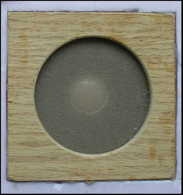
A piece of nylon screening, along with some pantyhose over the opening, keeps poking pieces and dust out of the speaker enclosure.  Otherwise, the speaker could be readily damaged as we move our modules around. 

With everything nicely dry-fitted, Colin soldered two wires about 12" long to the terminals on the speaker and pushed them through a hole we had drilled on an angle through the Styrofoam.  Some carpenter's glue put everything together. 

With the HQ300 sound unit mounted to the underside, the 2 1/2" speaker assembly installed alongside, and the NCE BD20 block detector previously installed, we were now ready to wire everything together.

We first tapped two wires into the auxilliary power buss and ran them to the HQ300 screw terminals marked "POWER".  (Polarity doesn't matter.  Voltage can be AC or DC.  Voltage must be 9-12 volts.) 

Next up was to connect the two speaker wires to the HQ300 screw terminals marked "SPEAKER".  As the wires were longer than required, we trimmed them back so that they were snug to the module deck.  (Better to have more wire than not enough, eh!?) 

To make sure everything was in order, we jumpered a wire between Screws 1 and 2 of the MOM/LOOP terminal block.  Eureka!  Bell ringing sound!  We adjusted the orange VOLUME control until we were satisified with the loudness of the sound. 


We lastly ran two wires from Screws 1 and 2 to Screws 2 and 1 of the BD20.  VERY IMPORTANT!  Make sure that the wires from the
  • HQ300 Screw 1 is fastened to Screw 2 of the BD 20, AND
  • HQ300 Screw 2 is fastened to Screw 1 of the BD20.

We were now ready for action!  We turned on the track power, powered up the 12 volt auxilliary buss, and slowly ran a train down the tracks towards the insulated block section.

As soon as the locomotive's wheels entered the block section, the lights on the grade crossing masts started flashing

 .......AND.........  the bell started ringing!!  Eureka!!  It works! 

And as the last of the locomotive's wheels left the block section, everything went silent.

Nothing like success, eh!?  Don't ya just love it when a plan comes together.

Here's a coupla more videos of the level crossing. 

(Colin C shot these videos of the train running through the level crossing.  Ya shoulda seen the big ear-to-ear grin on his face.  Now he's thinking about cow sounds, honky tonk piano and hurdy-grudy sounds, to say nothing of the industrial sounds that can be added.  Goes to show ya that the sky's the limit, eh!?)

The Peco Electrofrog - Circuitry

The electrical routing of the Peco Electrofrog is as different from the Insulfrog as day is to night.  I wouldn't even try to compare the two.  It's worse than comparing apples to oranges.  Let's take a look at the Peco Electrofrog so that we can understand how it works electrically.
At first glance, the Electrofrog is a nicely designed turnout.  Except for the guard rails, there is no plastic for wheels to run on.  It's completely Code 100 (or 83 or 70) nickel silver rail.  It's a beautiful turnout.  When weathered, ballasted, and scenicked, you don't even notice the oversize ties, tie plates or track spikes.  The positive locking action of the switch points makes it the ideal turnout for anyone's layout.

When it comes to using DCC, there are a couple of problems.  The solutions, however, are relatively simple. Let's first take a look at how the power is routed in the Electrofrog so as to get a better understanding of the operation of the turnout.

Power-Routing In An Unmodified Peco Electrofrog
The Electrofrog was originally designed for the days of analog when we wanted to power sidings based on which way the points were thrown.  We could drive a locomotive into the siding and then set the points for the mainline route.  We could rest assured that the locomotive wouldn't creep away on us - assuming there were no track feeds in the siding.  We could then flick another turnout that held another locomotive and we could then drive that new locomotive.  This ability had everything to do with how the Electrofrog was wired - By a combination of the rails and wire bonds on the underside, the points acted as a switch that routed the power to either the mainline route or the diverging route.

While it wasn't obvious, if the points were set for the mainline route, a whole lot more than just the mainline route was electrified.  In the bottom half of the photo below, we've traced the electrical polarity in blue and red.  Take a look at the red rails.  Hard to believe that all of these rails, particularly the point and diverging rails on the diverging route are also powered when the points are set for the mainline route!  
If we now throw the points for the diverging route and trace the electrical polarity, we see that a similar situation exists. Notice how the polarity of the points and the inside mainline and inside diverging rails have changed from red to blue!
 This how the Peco Electrofrog handles power-routing.

The advent of DCC, however, got rid of the concept of power-routing.  Locomotives only moved when we told them to move (via the throttle).  When we parked them, they stayed parked, even though there was still  power in all the rails.  We also added all kinds of track feeds beause we didn't have to worry about power-routing any sidings, particularly around turnouts.

Good DCC wiring practice requires us to have track feeds before the points and track feeds after the frog on both the mainline and diverging routes.  Which caused problems with the Peco Electrofrogs.  Because the points power-routed the power, and depending on how things were wired, the Electrofrogs shorted things out.  Let's take a look at an unmodified Electrofrog and see how this happens. 

DCC And Shorting In the Electrofrog
In the photo below, we've added our track power buss and the track feeds before the points and after the frog and set the points for the mainline route.  You can see that doing this creates a major short at the frog where the red current on the inside mainline rail crashes into the blue current of the inside diverging rail - electrically speaking, that is.   
 And if we look at the electrical routing when we set the points for the diverging route, we have the same thing happening - a major electrical short!

How can we get rid of the electrical short in the Electrofrog.  Let's take a look at the first of a 4-step process.  The mods are simple.

Step 1 - Insulated Rail Joiners After The Frog - Mandatory!!
In addition to adding track feeds before the points and another set after the frog on both the mainline and diverging routes, our first step is to add insulated rail joiners on the inside mainline rail and the inside diverging rail. (If your turnouts are already installed, simply cut gaps in the rails after the frog and fill the gaps with epoxy.)

When we set the points for the mainline route, the points of the Electrofrog continue to power-route the power as before.  However, because we've added an insulated rail joiner on the inside diverging rail, we no longer have a short, notwithstanding that both point rails, the straight closure rail and curved closure rail have the same red polarity.
When we set the points for the diverging route, the points of the Electrofrog continue to power-route the power into the diverging route.  And, because we've added an insulated rail joiner to the inside mainline rail, we no longer have a short, notwithstanding that both point rails, the straight closure rail and the curved closure rail have the same blue polarity.
As a minimum, if you are using the Peco Electrofrog, you HAVE to install the insulated rail joiners on the inside mainline rail and the inside diverging rail.  Or gap these rails and fill the gaps with epoxy or styrene.  NO EXCEPTIONS!

We still have the problem, however that the wheels of our locomotives may short out on the point rails.  This is especially true for steam locomotives and 6-axle diesels  Taking a look at the above two photos, the red point rail shorts out on the mainline blue rail as the loco goes through and the wheels span the gap between the two.  OR, the blue point rail shorts out on the red diverging rail as the loco goes through and the wheels span the gap between the two.  If you still don't see how this happens, take a look at the graphic below.
To fix this problem, we have to go to Step 2 where we slightly modify the wiring of the Electrofrog.  

Grade Crossing Signals For HO & N-Scale

While Colin C and I were at the Springfield train show in January of 2010, Colin expressed an interest in getting some grade-crossing signals for his "Crundale" modules.  Colin and I are both members of Ottawa Valley HOTRAK where we've been experimenting with some of the new electronic gadgets that have appeared on the model railroad market over the last couple of years.

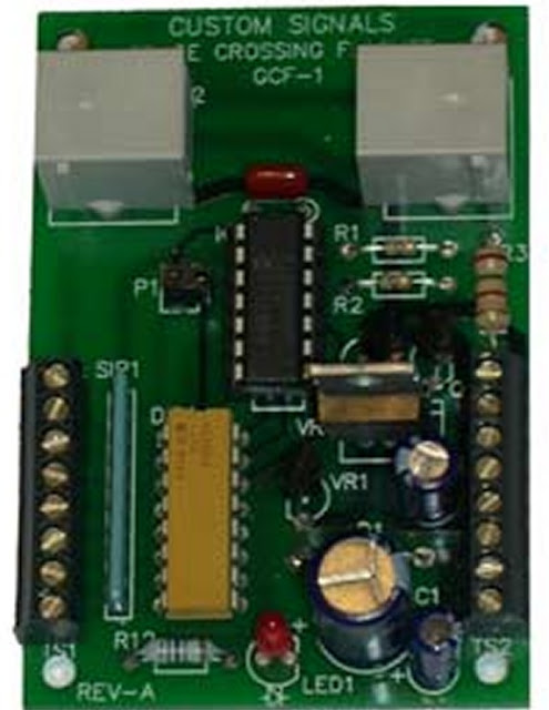
Custom Signals has a nice plug-n-play grade crossing signal, complete with signal masts and circuitry.  In addition to the prototypical pause of the LEDs in their flash cycle, I particularly like the fact that the wiring for the masts is an RJ12 telco plug that plugs into an on-board jack on their GCF-1 printed circuit board.

The wiring of the signal mast is very easy to follow.  The LEDs are wired in an "X-pattern" so that they flash on-and-off prototypically as shown in the schematic below.  First the ones on the left (when facing the fronts of the signal mast), then the ones on the right (when facing the fronts of the signal mast).  Just like the real thing. And there's that nice pause in each light as the other light starts to light up. 
And the wires are nicely colour-coded to correspond with the wiring of an RJ12 6-wire telephone cable.  Only difference is that instead of using 6 wires, the signal mast only needs three - black, green, and yellow.  FYI, here's the wiring standard for 6-wire flat telephone cable.  (We'll discuss the crimper later on.)

Only one problem.  The signal mast is O-scale which is kind of tall for anyone in HO or N.  So how could we use the nice Custom Signals circuitry on the GCF-1?  The answer is very simple.  NJ International (NJI) makes a series of grade crossing signal masts that are wired common anode (positive) which is the same return polarity as the GCF-1.  

The NJI signal mast is nicely proportioned and pre-wired with two 150 ohm resistors.  With the same common anode (positive) return polarity as the Custom Signals GCF-1 flasher unit, this should make a good pair.

The first step was to determine which wires lit up the LEDs - ie which wires were negative and which wires were positive.  One of my "testing utilities" is a 9-volt battery with alligator clips soldered to the ends of the wires.  In between the battery and the clips is an SPST on-off switch and a resistor.  Whenever I want to test the polarity of an LED, I simply clip the clips onto the LED and flick the switch.  If it lights up, a quick glance at the symbols on the side of the battery tells me which wire is negative (cathode) and which wire is positive (anode).   As it turns out, the black wire is positive (anode) and the two white wires are negative (cathode).  Here's a schematic of the wiring for the NJI grade crossing signal mast.

With the wiring problem out of the way, we next turned our attention to detecting the presence of a train.

The Custom Signals GCF-1 is designed for 3-rail O-gauge so the on-board detector is not compatible with HO or N-scale DC or DCC.  As I'm into Digitrax DCC, I needed a detector that would work with DCC.  North Coast Engineering (NCE) makes a nice BD20 block detector that is based on the current flow through a small toroid transformer.  Adding the detector to the module would be a very simple job - simply cut the track feed to the insulated block that defined the grade-crossing signal zone, thread the wire once through the donut-hole in the detector and resolder the wire back to the other end of the track feed. The detector is so sensitive that all it needs is for the wire to pass through the donut-hole only once and not the 3-4 times shown in the schematic below.  Having looked at the BD20 brochure, it was easy to determine the connections we had to make back to the GCF-1. 

However, before we started the install, we took a one-inch long 3/8" diameter wooden dowel and drilled a 3/16" hole through the middle.  We then threaded the 3 wires (two white, one black) through the hole and epoxied the signal mast to the wooden dowel.  abc

Installing RJ12 Telco Jacks - Part 3 Installing The First Telco Jack

Now that we have the first telco jack wired up, we are ready to install it into the module frame.  Stuff both of the cables through the cutout in our module frame so that they are on the inside and underside of the module.  Then carefully remove the masking tape from the cables and our jig.  The operative word here is "carefully" as we have a bunch of very fragile wires that could create some headaches if we manhandle them.
Turn the telco jack around so that it's face-up in our recessed hole.  Drill two pilot holes in the faceplate with a 1/16" drill and screw the telco jack to the module frame with two #8 x 3/4" screws.
Carefully turn the module over so that the telco jack is on our work surface.  We next nail in two wire staples under each cable so as to hold it in place and to take the strain off of the wires.
Next, thread the wire through the slot in the middle cross member and over to the hole for the other telco jack.  Keep the wire in place with wire staples as required.  We want our LocoNet wiring to be as neat as possible so that it won't snag on car seats, hooks, tie-downs, boxes, or other things that could rip out this wiring.
Next, taking the other cable that's going to go to the end of the module, staple the cable to the module frame so that it's as close as possible to the Styrofoam.  We'll be threading the cable along the surface of the Styrofoam to the module end using some polyurethane glue.   
We next twist and bend the cable so that it arrives at the module end as shown below.  We keep the cable in place with temporary strips of duct tape.  Next apply gobs of polyurethane glue on each side of the cable about 5"-6" apart and spray the glue with water.  After an hour or so, the glue has set up.  If necessary, add more gobs of glue and water.  This is what our cable should look like before we've removed our strips of duct tape.
And here's another view of the same thing showing our installed telco jack, the cable to one end of the module, and the other cable threading its way to the telco jack on the other half of our module.
Next up - installing the other telco jack. 

Installing RJ12 Telco Jacks - Part 2 - Soldering The First Telco Jack

Now that we have our telco jack and two cables securely taped to our jig, we're ready to start soldering the wires together - white-to-white, black-to-black, red-to-red, green-to-green, yellow-to-yellow, blue-to-blue.  This can be a very tedious job so if you happen to lose patience or get tired, take a break.  Come back to finish it off another day.

We now have our four white wires pulled out and in the clear.  This is what our setup in our jig should look like - the 4 white wires (2 from the 2 cables and 2 from the 2 telco jacks) ready to be stripped, soldered and shrink-tubed. 

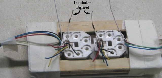
The first step is to remove about 1/2" of insulation from the two white wires from the telco jack.  I ALWAYS use a BBQ lighter and burn off the insulation.  I've tried using wire strippers, pliers, cutters, etc and I've always regretted it.  My BBQ lighter always does the job - no muss, no fuss, and no broken strands of wire.

I first burn about 1/2" of the insulation off of the two wires from the telco jacks.  The plastic insulation may either melt, or it may simply burn and leave black charred plastic behind.  If it's black charred plastic, simply scrape it off the wires with your cutters or some sandpaper.

Next I twist the two telco jack wires together - WHITE-to WHITE!!!  Always the same colour!

The 2 white wires from the cable might be a bit long (you don't want them short!) so I cut them back so that they lie flat on the body of the jack with a 90° bend where they'll join the 2 wires from the telco jacks that I just twisted together.  Using my Sharpie marker, in turn, I mark the white wires at a point where I will melt the plastic so that I will have bare wires.  I melt the plastic with my BBQ lighter.  I next twist these 2 wires from the cable around the 2 wires from the jack
I then solder these 2 wires together - first apply some flux, then some solder.
You'll notice that I have a blob of wires and solder at the top.  I simply cut this blob off with my cutters so that I have a nice, neat package of 4 white wires all soldered together.  Notice the difference between the photo above and the photo below. 
 I next slide a piece of shrink tubing over the top and push the tubing down as far as I can so that I have no bare wires showing.   I then shrink the tubing with my BBQ lighter.  I may have an excess of shrink-tubing over the wires.  I cut this excess off while the tubing is still warm and then gently squeeze the tubing together with my cutters or pliers so that the top is closed.  I now have a package of wires that is solidly connected and neatly insulated. 
 I repeat the process again with the black, red, green, yellow, and blue wires, each in turn.  The key is to do them in the order indicated so that we don't have wires crossing over each other.  Here we are halfway done - white black, red, green wires all soldered and all shrink-tubed.  You can see how we are starting to get a nice, neat package.   
And here's what the final product looks like with all wires soldered and shrink-tubed.
We're now ready to install this telco jack into our module.

PS - You may have recently bought your crimper and you're all set to crimp an RJ12 plug onto the end of the wire.  Only problem is, which wire goes into which side.  Does the blue wire go into the left side, or, does it go into the right side.  And after you've got the first plug crimped and you're all set to crimp on the 10th plug, how can you remember whether the white wire goes on the left or the blue wire goes on the right.  Here's an easy memory jogger tip that will solve that problem.  I take a dab of white paint (for the white wire) and a dab of blue paint (for the blue wire) and put the dab of paint on the crimper.

 And just in case you want to get your head around the Digitrax LocoNet wiring standard, here's my schematic of the standards.  If you twist your head sideways and upside-down, and look at the male plug, you'll see why, when facing the front of the crimper, we put the blue dot on the left and the white dot on the right.   
Hope this helps. 

PS - Don't buy plastic crimpers as they're only reliable 75% of the time.  It's that other 25% that's gonna cause you lotsa grief.  With plastic crimpers, you can't get that extra squeeze to lock the blades in the male plug tightly onto the coloured wires. 

Legs For The Modules

How Long Are The Legs?
So far, we have a module that can only sit on the floor.  We need to fabricate some legs so that we can get the module raised up to operating level.  

The legs are made from 2"x 2" (which is really 1 1/2"x 1 1/2") spruce lumber that is available in any building supply/ lumber store.  Usually 2"x 2" spruce gets a bad rap because of the tendency of spruce to warp and twist.  However, it's all in how you finish the spruce that makes all the difference. 

I get the 2"x 2" cut to length at the saw service of my local lumber store.  I then take them home, fill in any cracks, imperfections, etc with wood putty or epoxy glue.  I then give them a good sanding.  You'll find that a 2"x 2" is good on three sides.  It's that fourth side that will require a lot of attention.  If you have access to a belt sander, the job is easy - a couple of passes along each side will do the trick.  However, if all you have is some sandpaper, it will take a bit longer to smooth things out.  The effort you put into sanding the legs will be well worthwhile.  I find that a good sanding, filling and then sanding the splits and cracks again can turn a rough piece of lumber into a smoothly finished leg.

If you have access to a "chop saw" (aka a "mitre saw") it's very easy to set up a "stop block" and cut a whole bunch of legs to the proper length.  An 8' length of 2"x 2" costs about $5=$6 so it's always a good idea to pick up a couple of extra pieces.  You're going to find that, as we fabricate the legs, a couple of the legs will try to twist and warp before we get them finished.  This way, if we have a couple of extra pieces, we can discard the twisted pieces. 

The question now is "How long do I cut the 2"x 2"s?".  A good question!  There are several things to consider.  The thickness of the track and roadbed, Styrofoam, and gussets are quite obvious.  What's not so obvious is the "thickness" of the leg leveller when screwed completely into the leg, and the amount of "travel" required to adjust the module to account for imperfections in the floor.  If you belong to a module railroad club, you have a club standard that's usually expressed as a "plus-or-minus-so-many-inches".  In my case, the plus-or-minus is 1 1/4".  That means the leg leveller has to be capable of being unscrewed out an extra 1 1/4" or screwed in 1 1/4".  Here's a table that I use to calculate the length of the 2"x 2"s, taking into account all the above into consideration.  I've left a couple of columns for you to do your calculations. 
Thickness of Components Mine  Decimal Yours Decimal
Track 1/8" 0.125" . .
Roadbed 1/8" 0.125" . .
Styrofoam 1½" 1.50" . .
Cross Member 3/4" 0.75" . .
Leg Leveller When Screwed Into Leg 1/2" 0.50" . .
Leg Leveller Adjustment 11/4 1.25" . .
                Sub-Total 3 3/4" 3.75"  . .
Less Height From Rail to Floor 45" 45.00" . .
Equals Length of Wood for Legs 411/4" 41.25"  . .


Bundling The Wood
Once I have the legs cut and sanded (or if for any reason, you can't work on the legs right away) I bundle them up and wrap them in duct tape - at each end and in the middle - and leave them in a cool dry place for about 2 weeks.  The 2"x 2" right from the store has usually been bundled up which prevents the individual 2"x 2" from twisting and warping.  The minute the bundle is broken, they'll start to twist in every direction.  That's because the wood hasn't completely dried out.  By bundling them in duct tape and leaving them for a couple of weeks, most of the legs will have the chance to dry out straight. 
Better yet, if I clamp the wood together on all four sides and then bundle them up with duct tape, I usually end up with a complete set of legs that are nice and straight.

Locating The Centres
After sanding each side and filling the splits and cracks, the next step is to locate the centre on each end of the leg.  Simply draw a diagonal from one side to the other with a ruler.  Here's what a set of 16 bundled legs look like after drawing the lines.  I've already done the same at the other end. 

Painting The Legs
At this point, I could start to drill holes and then paint the legs but I've found it's a lot easier and less messy if I paint the legs first.  Since I'm working on 16 legs, I can take steps to "mass produce" them.

After locating the centres of each end of the legs, I next hammer a 2" nail about 1/2" into the wood.  This nail serves as a "peg leg" when I paint the wood.  I can use the "peg leg" to flip the wood from side to side as I swab on the paint.

I next take a nail (in this case 16 nails) and twist a 10"-12" length of wire onto the end (this is how I use some of that surplus telephone wire).  I then hammer the nail about 1/2" into the centre of the opposite end of each leg.  The wire makes a handy-dandy hanger-upper as I finish painting each leg.  . 

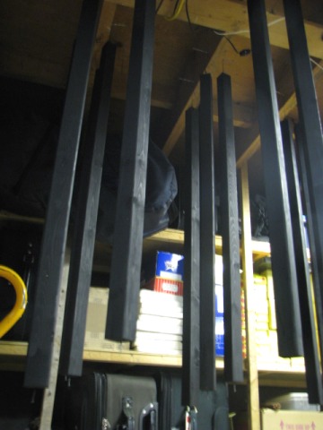
Since I do my painting in my basement, I next nail sixteen 3" nails into the sides of the floor joists in the basement.  I can then twist the wire around the 3" nails in the floor joist.  This keeps each leg nicely out of the way of the others.  I paint all four sides of each leg in operation.  As I finish painting a leg, I hang it up by the wire on one of those 3" nails in the floor joists.  Here's what 24 painted legs look like hanging from the joists.  Quite a difference, eh!? 

After the first coat of paint has dried, I lightly sand the legs to get rid of the fuzzies.  I then apply another coat of paint and hang each leg up to dry. I like to give each leg three coats of paint.  Since I'm doing 16 legs in one shot, I painted the legs using a small roller and a paint tray.  In three evenings of work, letting each coat of paint dry overnight with a light sanding between coats, I soon had my legs finished. 
If for any reason, you aren't going to be doing the next steps right away, after 10-12 days of drying, bundle up the legs and wrap some duct tape around the bundle at each end and in the middle.  This will prevent the legs from twisting and warping.   Even better, bundle up the legs, clamp all four sides together tightly, and then wrap some duct tape around the bundle at each end and in the middle.  

Drilling The Holes

After painting, I drill a 3/8" hole that's 1 1/4" deep in one end of the leg and a 9/32" hole (ie 1/32" smaller than 5/16") that is 1 1/4" deep in the other end.

We're going to epoxy a 5/16" T-nut into the 3/8" end.  Next, we'll thread an adjustable leg leveller into the T-nut.  Floors in basements and halls are never level and the leg leveller will help us to get rid of the "ski jumps" between modules.

At the 9/32" hole, we're going to screw in a modified 5/16" carriage bolt which will be epoxied in place.  The leg-ends with the modified carriage bolt will be screwed into the T-nuts in each corner of our module frame. in a T-nut so that our module can stand up on its own legs. 

Drilling holes in the ends of wood that's 1 1/2"x 1 1/2" is not easy.  This is where a drill press with a moveable table comes into play.  Or perhaps a jig for my cordless drill which I haven't yet figured out how to make.  Perhaps it's only with a steady hand and a good eye that you might be able to get those holes drilled.  If anyone has any ideas for a jig for a drill, I'd be most interested in hearing from you.

Installing The Leg Levellers
After all the holes have been drilled, I coat the barrel of the T-nut with epoxy, insert it into the hole and tap it into place with my hammer and let the epoxy set for 24 hours. 
Modifying Carriage Bolts
I next modify some 2 1/2" carriage bolts.  I cut the head off so that I have a "threaded rod" that is 2" long.  I then round the cut end using a bench grinder and/or a file so that I get rid of the sharp edges from my cut.

Carriage bolts have a thread that go from one end to the other whereas threads on regular bolts are only 1" long.  I need a threaded bolt that I can insert into the 1 1/4" hole with 3/4" sticking out.  The carriage bolt epoxied into the hole will do the trick.

You may be tempted to get a long threaded rod and chop it up into 2" pieces.  DON'T!  When you cut the threads, you'll have a jagged cut at both ends which, in spite of any filing you might do, will remain jagged on the thread which will eventually tear the thread in the T-nut.

For the next steps, you need to identify which end is the "cut-end", and which end is the "finished end" of the cut carriage bolt.  The photo above will help you to identify which is the "cut-end" and which is the "finished end".

Installing Modified Carriage Bolts
To install the cut carriage bolt, I first tighten two 5/16" nuts against each other at the "finished end" using two 1/2" wrenches.  I then load the drilled hole with epoxy, insert the threaded end into the hole, and crank it home with one wrench until only 3/4" of the thread is sticking out of the hole.  Again using the two wrenches, I undo the two nuts and repeat the installation process for the other legs. 
 Still with us?

We now have a set of legs with a leg leveller in one end (the bottom) and a threaded piece of rod in the other end (the top end).  With the module on its side, insert the threaded rod into the T-nut on the underside of the module and tighten it in.  With some help from a friend, lift the module up and set it on its legs.

Voila, the module now has legs!